YoboGo quadruped motion control
Motion-control integration and Up Board bring-up with an MIT Mini Cheetah-derived stack at Geely Research Institute.
Stack: C++ · Linux · Up Board · LCM · MIT Mini Cheetah-derived control
Where: Geely Research Institute, 2022
During my internship at Geely Research Institute, I worked on motion control for the YoboGo quadruped. The robot used an existing C++ control stack derived from MIT Mini Cheetah software, running on an Up Board.
What I worked on
- Motion control — working with the existing quadruped control software and its integration on the target computer.
- Target bring-up — the Up Board Linux environment and the dependencies needed to build and run the control stack.
- Software interfaces — working with the stack’s LCM-based command, state and logging interfaces.
Team context
The team divided motion control and perception across two computers. My focus was the Up Board motion-control side; colleagues handled SLAM and LiDAR on a Jetson. This experience shaped my interest in the practical interface between control software, the target computer and a moving robot.
Inside the control stack
The diagrams below explain the public MIT Cheetah reference software that underpins this family of controllers. They describe inherited software concepts; my contribution remained motion-control integration and target bring-up. The reference revision is pinned in the source links below.
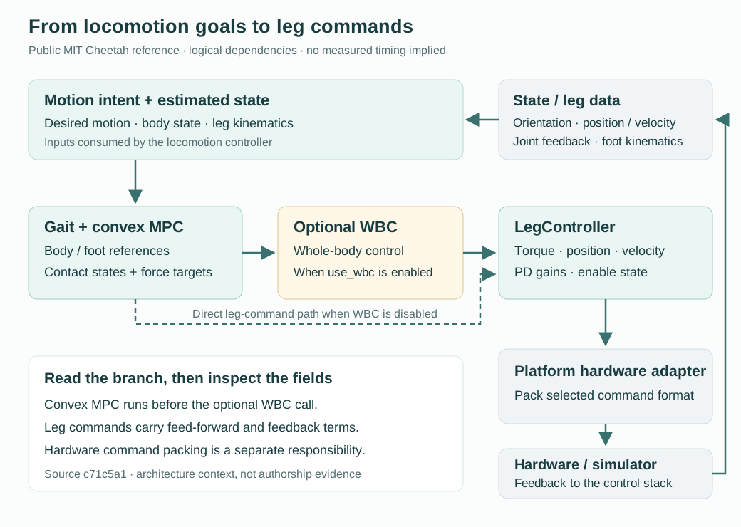
Planning forces, then forming leg commands
In the reference locomotion state, ConvexMPCLocomotion runs first. It supplies desired body motion, foot trajectories, contact states and ground-reaction forces. When use_wbc enables whole-body control, these references are passed to LocomotionCtrl; otherwise, the MPC-generated leg commands remain the direct control path. This distinction matters when tracing which component produced a particular target or gain.
The lower layer groups each leg’s feed-forward torque, foot-force reference, position/velocity targets and PD gains in LegController. The hardware adapter then packs the appropriate platform command. This diagram expresses software dependencies, rather than an as-built YoboGo wiring layout.
Source: public locomotion state.
Inspect one control iteration
In the pinned RobotRunner::run() revision, the order is:
- Run the state estimator using the data currently held by its inputs.
- Call
setupStep()to refresh leg data and clear the previous command buffer. - Apply the mode, enable and initialisation logic before invoking the controller.
- Run the selected controller and update visualisation data.
- Call
finalizeStep()to pack commands and publish telemetry.
The estimator call precedes setupStep() in this revision. The diagram above is therefore a dependency map, not a sensor-to-actuator timing trace. No measured loop frequency or latency is claimed here.
Source: public runner and estimator setup.
State estimates and coordinate frames
The normal reference estimator setup combines contact estimation, VectorNav orientation and LinearKFPositionVelocityEstimator. The latter estimates body position and velocity using inertial acceleration and leg kinematics; contact phase changes how strongly foot observations are trusted. These are components of the inherited stack, separate from my personal contribution.
The leg interface uses a frame aligned with the body and originating at the leg’s hip pivot. World-frame body or foot references must therefore be handled with the appropriate transformations before reaching this interface.
Sources: public position/velocity estimator, leg-frame convention.
From a foot-force reference to joint torque
For the public Mini Cheetah SPI command packer, the host combines a feed-forward foot force with Cartesian position and velocity feedback:
Here, $p$ and $v$ are foot position and velocity in the leg frame, $J$ is the leg Jacobian, and the subscript $d$ denotes a desired value. Joint targets and diagonal joint PD gains are packed separately. The host’s tauEstimate adds the joint PD terms to the packed torque; it is a computed estimate, not a torque-sensor measurement.
Source: public leg-command packing.
Making the system observable with LCM
LCM provides typed publish/subscribe messages, generated encoding/decoding, and tools for recording and replay. In the public runner, the three channels below expose a snapshot of commands, leg data and the estimated body state. Those snapshots make it possible to compare what the controller requested with the state available to it.
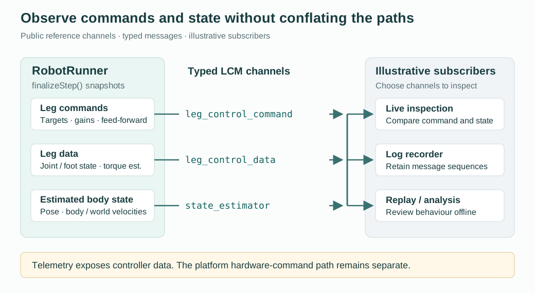
Despite its name, leg_control_command is published here as command telemetry after the platform command has been packed. Its presence alone does not identify the physical motor bus or establish an LCM actuator-command path.
Inspect the message contents
| Channel | Representative fields | What to inspect |
|---|---|---|
leg_control_command | Joint/foot targets, feed-forward terms and gains | Whether the intended command is populated |
leg_control_data | Joint position/velocity, foot position/velocity, estimated torque | Signs, offsets and consistency with the requested motion |
state_estimator | Position, quaternion, roll/pitch/yaw and body/world velocities | Frame conventions and changes in the estimated body state |
The public command and leg-data schemas use flattened 12-element arrays; the state schema uses named body/world vectors. These field layouts describe the reference messages.
Sources: LCM documentation, command schema, leg-data schema, state schema.
Integration questions this architecture makes concrete
- Target build: are the model, controller executable, dependencies and generated message bindings consistent with the selected target?
- Feedback: do joint signs, zero offsets and coordinate frames agree with the model before motion is enabled?
- Control path: is the active controller branch producing the expected targets and gains?
- Observability: do recorded command and state messages support the behaviour seen on the robot?
These are integration checks suggested by the architecture. They are not a record of measured acceptance results from my Geely internship.
No proprietary Geely material is reproduced here.